- Layer 2 uses MAC addresses and is responsible for packet delivery from hop to hop.
- Layer 3 uses IP addresses and is responsible for packet delivery from end to end.
Switch Functions:
A Switch primarily has four functions: Learning, Flooding, Forwarding, and Filtering:
Learning:
The MAC address table starts out empty, and every time a Switch receives anything, it takes a look at the Source MAC address field of the incoming frame. It uses the Source MAC and the switchport the frame was received on to build an entry in the MAC Address Table.
Flooding
the Switch’s only option is to simply duplicate the frame and send it out all ports. This action is known as Flooding.
Flooding assures that if the intended device exists and if it is connected to the switch, it will definitely receive the frame.
Forwarding
the Switch will have an entry in its MAC Address Table for every Destination MAC it comes across.
When this happens, the Switch happily forwards the frame out the appropriate switchport.
There are three methods by which a Switch can forward frames.
Store and Forward – The Switch copies the entire frame (header + data) into a memory buffer and inspects the frame for errors before forwarding it along. This method is the slowest
- Cut-Through – The Switch stores nothing, and inspects only the bare minimum required to read the Destination MAC address and forward the frame. This method is the quickest, but provides no error detection or potential for additional features.
Filtering
And finally, the last function of the switch is filtering. Mainly, this function states that a Switch will never forward a frame back out the same port which received the frame.
Example:
Initially, the MAC Address Table of the Switch is empty. Remember, it only gets populated when a frame is received.
Host to Host Through Router
--------------------
Host A getting the Packet to R1
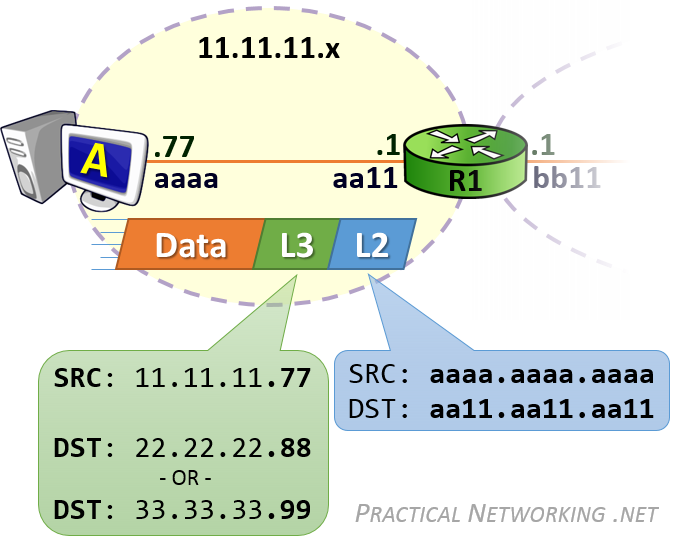
Host A will create the L3 header with a Source IP address of 11.11.11.77, and a Destination IP address of 22.22.22.88 (for Host B) or 33.33.33.99 (for Host C). This L3 header will serve the purpose of getting the data from ‘end to end’.
Host A will then encapsulate the L3 header in a L2 header which will include a Source MAC address of aaaa.aaa.aaaa and a Destination MAC address of aa11.aa11.aa11 — the MAC address which identifies R1’s NIC. This L2 header will serve the purpose of delivering the packet across the first hop.
Host A will have already been configured with its Default Gateway’s IP address, and hopefully Host A will have already communicated with foreign hosts. As such, Host A more than likely already had an ARP Table entry with R1’s MAC address. Conversely, if this was Host A’s first communication with a foreign host, forming the L2 header would have been preceded with an ARP Request to discover R1’s MAC address.


For the packet from Host A sent to Host C, the Destination IP address will be 33.33.33.99. When R1 consults its Routing Table, it will determine that the next-hop for the 33.33.33.x network exists at the IP address 22.22.22.2 — R2’s left interface IP address.
Should R1 not have R2’s MAC address, it would simply initiate an ARP Request for the IP address in the route: 22.22.22.2. From then on, it will have no problems creating the proper L2 header which will get the packet from R1 to R2.
No comments:
Post a Comment