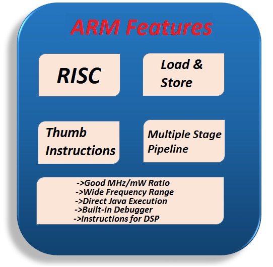
ARM Processors are based on reduced instruction set computing (RISC) architecture.
ARM Processors follow Load and Store type architecture where the data processing is performed only on the contents of the registers rather than directly on the memory. The instructions for data processing on registers are different from that access the memory.
The instruction set of ARM is uniform and fixed in length. 32-bit ARM Processors have two instruction sets: general 32-bit ARM Instruction Set and 16-bit Thumb Instruction Set.
ARM supports multiple stages of pipeline to speed up the flow of instructions. In a simple three stage pipeline, the instructions follow three stages: fetch, decode and execute.
Some of the general features of ARM are listed here.
- ARM Processors have a good speed of execution to power consumption ratio.
- They have a wide range of clock frequency ranging from 1MHz to few GHz.
- They support direct execution of Java bytecodes using ARM’s Java Jazelle DBX.
- ARM Processors have built in hardware for debugging.
- Supports enhanced instructions for DSP operations.
The Thumb instruction set consists of 16-bit instructions that act as a compact shorthand for a subset of the 32-bit instructions of the standard ARM. Every Thumb instruction could instead be executed via the equivalent 32-bit ARM instruction. However, not all ARM instructions are available in the Thumb subset; for example, there's no way to access status or coprocessor registers. Also, some functions that can be accomplished in a single ARM instruction can only be simulated with a sequence of Thumb instructions.
At this point, you may ask why have two instruction sets in the same CPU? But really the ARM contains only one instruction set: the 32-bit set. When it's operating in the Thumb state, the processor simply expands the smaller shorthand instructions fetched from memory into their 32-bit equivalents.
The difference between two equivalent instructions lies in how the instructions are fetched and interpreted prior to execution, not in how they function. Since the expansion from 16-bit to 32-bit instruction is accomplished via dedicated hardware within the chip, it doesn't slow execution even a bit. But the narrower 16-bit instructions do offer memory advantages.
The Thumb instruction set provides most of the functionality required in a typical application. Arithmetic and logical operations, load/store data movements, and conditional and unconditional branches are supported. Based upon the available instruction set, any code written in C could be executed successfully in Thumb state. However, device drivers and exception handlers must ---often be written at least partly in ARM state.
Register sets
When operating in the 16-bit Thumb state, the application encounters a slightly different set of registers. Figure 1 compares the programmer's model in that state to the same model in the 32-bit ARM state.

When operating in the 16-bit Thumb state, the application encounters a slightly different set of registers. Figure 1 compares the programmer's model in that state to the same model in the 32-bit ARM state.
----------------------------
General Purpose Input Output (GPIO) pins of a microcontroller are the first thing we need to learn before starting its embedded programming as input/output pins are the only way to interface with the microcontroller. GPIO pins can be used for driving loads, reading digital and analog signal, controlling external components, generating triggers for external devices etc.
Most of the pins in both the I/O ports have more than one function i.e. they are multiplexed with different functions. At any point of operation, each pin can have a single function and the function can be selected with the help of three Configuration Registers which control the multiplexers to allow connection between the external pin and the on-chip peripheral.
The GPIO function in both the Ports are controlled by a set of 4 registers: IOPIN, IODIR, IOSET and IOCLR.
IOPIN: It is a GPIO Port Pin Value register and can be used to read or write values directly to the pin. The status of the Pins that are configured as GPIO can always be read from this register irrespective of the direction set on the pin (Input or Output).
IODIR: It is a GPIO Port Direction Control register and is used to set the direction i.e. either input or output of individual pins. When a bit in this register is set to ‘0’, the corresponding pin in the microcontroller is configured as Input. Similarly, when a bit is set as ‘1’, the corresponding pin is configured as Output.
No comments:
Post a Comment