HOW UART WORKS
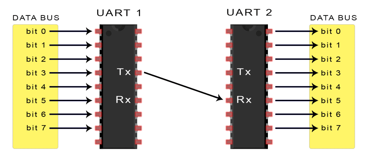
The UART that is going to transmit data receives the data from a data bus. The data bus is used to send data to the UART by another device like a CPU, memory, or microcontroller. Data is transferred from the data bus to the transmitting UART in parallel form. After the transmitting UART gets the parallel data from the data bus, it adds a start bit, a parity bit, and a stop bit, creating the data packet. Next, the data packet is output serially, bit by bit at the Tx pin. The receiving UART reads the data packet bit by bit at its Rx pin. The receiving UART then converts the data back into parallel form and removes the start bit, parity bit, and stop bits. Finally, the receiving UART transfers the data packet in parallel to the data bus on the receiving end:
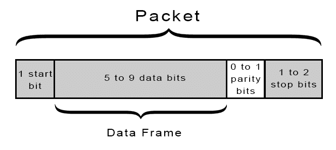
UART transmitted data is organized into packets. Each packet contains 1 start bit, 5 to 9 data bits (depending on the UART), an optional parity bit, and 1 or 2 stop bits:
START BIT
The UART data transmission line is normally held at a high voltage level when it’s not transmitting data. To start the transfer of data, the transmitting UART pulls the transmission line from high to low for one clock cycle. When the receiving UART detects the high to low voltage transition, it begins reading the bits in the data frame at the frequency of the baud rate.
DATA FRAME
The data frame contains the actual data being transferred. It can be 5 bits up to 8 bits long if a parity bit is used. If no parity bit is used, the data frame can be 9 bits long. In most cases, the data is sent with the least significant bit first.
PARITY
Parity describes the evenness or oddness of a number. The parity bit is a way for the receiving UART to tell if any data has changed during transmission. Bits can be changed by electromagnetic radiation, mismatched baud rates, or long distance data transfers. After the receiving UART reads the data frame, it counts the number of bits with a value of 1 and checks if the total is an even or odd number. If the parity bit is a 0 (even parity), the 1 bits in the data frame should total to an even number. If the parity bit is a 1 (odd parity), the 1 bits in the data frame should total to an odd number. When the parity bit matches the data, the UART knows that the transmission was free of errors. But if the parity bit is a 0, and the total is odd; or the parity bit is a 1, and the total is even, the UART knows that bits in the data frame have changed.
STOP BITS
To signal the end of the data packet, the sending UART drives the data transmission line from a low voltage to a high voltage for at least two bit durations.
ADVANTAGES
- Only uses two wires
- No clock signal is necessary
- Has a parity bit to allow for error checking
- The structure of the data packet can be changed as long as both sides are set up for it
- Well documented and widely used method
DISADVANTAGES
- The size of the data frame is limited to a maximum of 9 bits
- Doesn’t support multiple slave or multiple master systems
- The baud rates of each UART must be within 10% of each other
No comments:
Post a Comment